Network/Switch tab on LuCI WebUI Clusterbox Dashboard explanation

Good morning
Can you help me understand the tab in question?

Switch “switch0” (mt7620), ports: 8 (cpu @ 6)

What exactly does the wording “ports: 8 (cpu @ 6)” mean?

VLANs on “switch0” (mt7620), ports: 8 (cpu @ 6)
VLAN ID Description CPU (eth0) LAN 1 LAN 2 WAN

I understand that we are dealing with two VLANs (so not a simple error in history*):

Is VLAN 1 a VLAN between Blade3 N1 and Blade3 N2?
Is VLAN 2 a VLAN between Blade3 N3 and Blade3 N4?

So:

CPU(eth0) is the pcie network?
LAN 1 is something like br_lan?
LAN 2 ?
WAN is eth0.2?

*At first glance (and for about a little month thereafter) it immediately seemed to me “the antechamber of death of my control board” :slight_smile: :: a place where you touch something and you risk your salary in short!

By the way, what happens when I turn off the feature?

Thanks guys!!

You can refer to the following introduction.

The CPU (eth0) is the core of all ports and is used to manage VLAN data.

LAN (br-lan)

Ports 0 and 1 form the LAN.
Connect to the CPU through eth0.1.
Use 169.192.1.1 as the IP address

WAN (external network)

Port 5 is used as the WAN.
eth0.2 is responsible for connecting to the external network.
Obtain an address through DHCP.

VLAN

VLAN 1 (LAN): eth0.1, ports 0,1,6t.
VLAN 2 (WAN): eth0.2, ports 5,6t.

Device Name Type Function Notes
lo Virtual device Local loopback interface Only used for internal communication within the device
pci0 Physical device PCIe Ethernet PCIe network card
br-lan Logical bridge LAN port bridge Connects to eth0.1
eth0 Physical device Switch chip connected to CPU Responsible for all VLAN transmissions
eth0.1 VLAN device VLAN 1 (LAN) Connected to br-lan
eth0.2 VLAN device VLAN 2 (WAN) Directly connected to the external network
switch0 Switch chip Port management Responsible for VLAN allocation

about Blade3

The pci0 of mt7620 and Blade3 N1 ~ N4 pci0 form a LAN

It seems understandable and important to me.

I wonder: by disabling the service I will not run any risks, right? I gather the VLANs into a single LAN and keep all the services and connections active!?

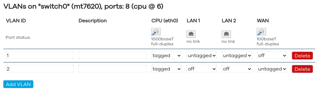
VLAN 1 (LAN): eth0.1, porte 0,1,6t.

Are ports 0 and 1 then the IPv4 and IPv6 of the br-lan interface?

VLAN 2 (WAN): eth0.2, ports 5,6t.

It makes me think that ports 5 and 6 refer to the IPv4 and IPv6 connections of our WAN interfaces.

Port 5 is used as the WAN.
eth0.2 is responsible for connecting to the external network.
Obtain an address through DHCP.

Is port 6 then shared between VLAN 1 and VLAN 2? In this case, can WAN IPv6 be useful to connect to the CPU in case the other interfaces unfortunately remain unavailable?

What exactly do LAN 1 and LAN 2 on the column refer to? Maybe to br-lan and eth_pci?

Even if the rest will seem trivial to me in comparison:

The pci0 of mt7620 and Blade3 N1 ~ N4 pci0 form a LAN

Does this mean that the Blade3 N1, N2, N3, N4 via pci0 and mt7620 via pci0 form a LAN? In this case, could you tell me why I can’t find them all in my “nmap 10.20.0.0/24”? To tell the truth, I always find them two by two, the one from which I connect Blade3 and the adjacent one; my problem was exactly that of being able to reach each one through a PCIe connection, perhaps without routing and forwarding.

I’ll try again tonight at home. Maybe I manually set the connection and despite having entered the DNS correctly, the /etc/hosts file takes precedence causing the correct routing to be missing (!?). In this case I can recommend to execute a cluster reboot via:

ssh clusterbox [editor’s note 10.20.0.1] nodectl reboot -all && sudo reboot.

Instead set the host names via WebUI Network/DHCP DNS or via the file on clusterbox /etc/config/dhcp. In fact it seems that a normal reboot of the ClusterBox following a disconnection of a Blade3 does not restore the initial correct situation, this also – by the way – by running DHCP as auto on Blade3 SBCs.

Thank you very much.

If VLAN 1 and VLAN 2 represent our VLANs, what do LAN 1 and LAN 2 represent?

This page seems “DANGEROUS” to me, what mistakes should I not make to avoid being “kicked out” of the dashboard forever?

Could you tell me the exact meaning of the terms tagged and untagged?

Thanks

I would like to try to configure the br_lan but there is something that escapes me. I have to associate an interface (or maybe two?) and then take or assign an address to the hosts that connect to it so as to have them all in the same network domain!? When I associate pci0 I lose the connection with the Blades and when I associate eth0.2 I lose connectivity with the WAN, I am afraid of being left without the possibility of interfacing with the dashboard. If used alone it seems isolated even if I connect the rear port to the network switch. Once again then (thanks a lot to anyone who wants to provide me with some information), what do LAN1 and LAN2 represent in the figure? What do tagged, untagged and off mean? How can I register a host on the br_lan network?
Thanks.

LAN1 LAN2 interface does not actually exist. Due to the speed limit of mt7620a network interface in clusterbox, it is not recommended to provide network to pci0 device through the wan of mt7620a. Its function is to use four blade3 as a LAN. The blade3 can connect to the external network through two 2.5G network ports.
Tagged

Ports carry traffic with VLAN tags (like labeled packages), used for connecting switches or devices handling multiple VLANs.

Example: Trunk links between switches to pass multiple VLANs.

​Untagged

Ports strip VLAN tags (like unlabeled packages), ideal for end devices like PCs/phones.

Assigns one default VLAN (PVID) to untagged traffic.

​Off

Ports completely block traffic for a specific VLAN.

Used to exclude ports from unwanted VLAN communications

With what I am about to say it is not my intention to try to confuse the ideas in any way.

I noticed that at the time of boot the Blade3 in the cluster form 2 separate networks while remaining in the same subnet domain, this regardless of whether a manual configuration or DHCP is used.

Sometimes we have N1 and N2 in connection (visible to each other in the same subnet) and N3 and N4 in connection (nmap 10.20.0.0/24) [or (N2 + N3) and (N1 + N4)]; while other times for example we have N1 isolated and N2, N3 and N4 in connection; this with “very obviousness” occurs among other things between adjacent Blade3. In the model just described (of a three-node network and an isolated node) then we will in fact have, for example, N2 connected to N3 and N3 connected to N4.

I also noticed that sometimes the subdivision occurs in this other configuration: N1 connected to N2 and N4, while N3 is isolated, I think this fact demonstrates that the switch actually fulfills its task perfectly, that is to put the nodes assigned to it in mutual communication.

As I was able to learn from a previous post by one of your team members (Bobby):

When using Blade 3 in the Cluster Box, two lanes of PCIe will work as RC(Root Complex) which connects with NVMe SSD if there is NVMe SSD installed, and the rest two lanes of PCIe will work as EP(Endpoint) which connects to the PCIe switcher.

https://community.mixtile.com/t/nvme-ssds-not-recognized-in-clusterbox/701

I wonder: if then as it seems, each Blade3 is connected via 2 PCIe lines to the switch (while 2x remain available for peripherals)…

Why then the choice of this configuration?

Why 2 transparent VLANs, not visible, not declared, unpredictable, not configurable nor modifiable?.. Separative and discriminatory internal policy towards souls and hearts once united under the same sky and now divided?! :slight_smile:

Thanks