Getting to know this gorgeous platform, can’t understand why “The PCIe daisychain solution also has a single point of failure: the whole cluster will go down if one node crashes.”
From my understanding, the clustering is really built over IP, so a node failure should in the worst case lead to a split cluster with 2 nodes on one side and 1 isolated node.
Still from my understanding, closing the loop between node1-portA and node4-portB should avoid that split brain issue.
Would some knowledgeable soul shed some light on this for me please?
Thanks in advance and fat congrats for this outstanding design.
Hello Silopolis, your understanding is correct that clustering is generally built over IP, and in typical scenarios, the failure of a single node should not bring down the entire cluster. Instead, it could lead to a partitioned cluster, also known as a “split brain” scenario, where the nodes cannot communicate with each other and thus may operate independently, which can cause data inconsistency or other issues.
However, as you suggested, creating a loop by connecting node1-portA with node4-portB could provide an alternative pathway for communication, which would help prevent a single point of failure. This setup would allow the cluster to remain operational by rerouting the communication through the alternative path, should one of the nodes or connections fail. It’s important to note that implementing such a loop would require additional logic to handle the rerouting of communication and to ensure that there are no conflicts or confusion in the data paths. This can be achieved through sophisticated cluster management software that can detect failures and dynamically adjust communication paths.
If you have any further questions or if there’s anything else we can assist you with, please don’t hesitate to reach out.
Hi @bobby
Thank you for your answer.
This triggered some searches about the possible ways of managing loops and rings at layer 2 (*STP, Shortest Path Bridging, Ethernet Ring Protection Switching, and TRILL) and layer 3 (ECMP)… but I realize I don’t fully understand how things are really “cabled” on the backplane of the cluster box!?
I presumed all PCI ports were bridged together sharing the same broadcast domain, is that right?
A video about configuring network on the box also makes me believe that the “BMC node” also has a leg on that bridge, true?
Also, in the case of daisy chaining, how’s the network configured? A bridge is created on each node with each network leg attached to it? Only the bridge gets an IP address?
On layer 2, my understanding is that only *STP is really supported under Linux. OpenWRT also offers a ustp package that may be become useful? Sadly, on the SPB/ERPS/TRILL front, these don’t look well-supported with old unmaintained or nonexistent implementations.
What cluster management software were you thinking about for failure detection? Some heartbeat/pacemaker kind of things?
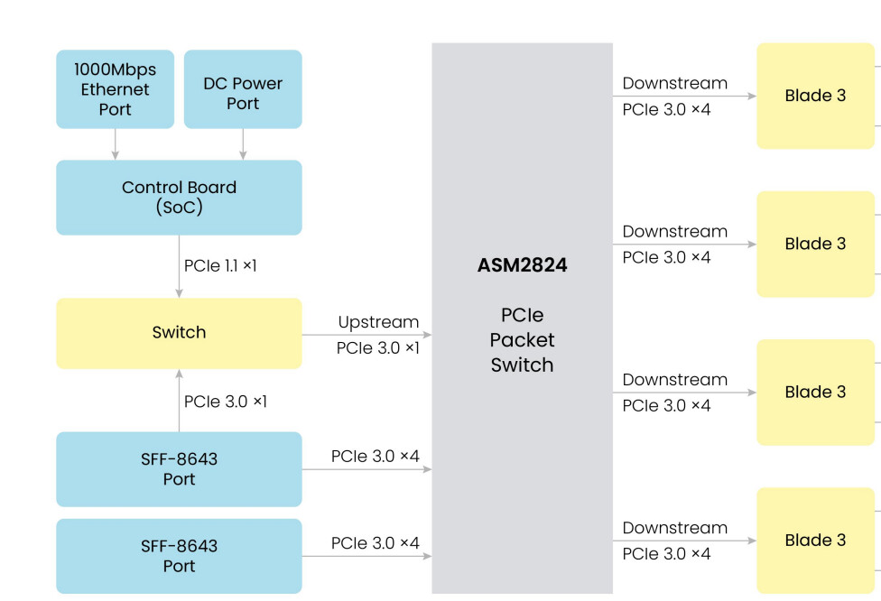
Hello Silopolis, the Cluster Box utilizes a PCIe Switcher chip to effectively connect four Blade 3 units. This configuration establishes the MT7620 on the control board as the PCIe root complex (RC), while the four Blade 3 units act as PCIe endpoints (EPs). We developed TCP/IP over the PCIe driver and each Blade 3 could get the exclusive IP address from the control board. The PCIe switching chip facilitates point-to-point connections and communication between multiple devices. Each device enjoys its dedicated connection, eliminating the need for bandwidth sharing, thereby enhancing data transmission efficiency. There is no daisy chain connection in this topology. You could refer to the diagram as below screenshot which is from the user manual of Cluster Box.
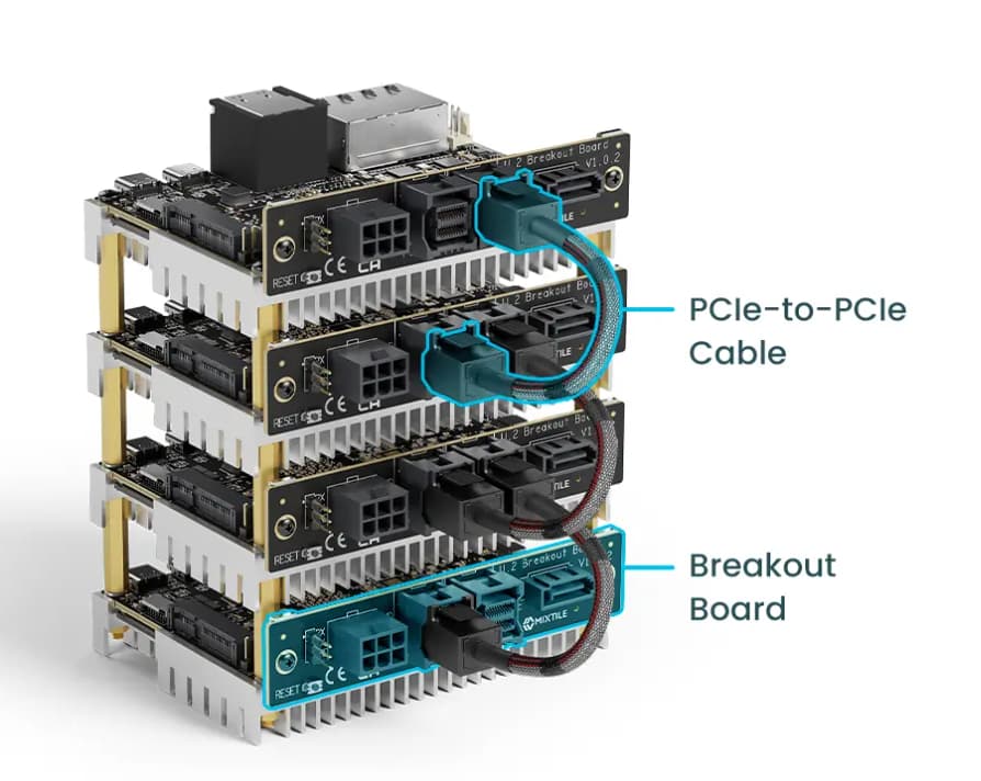
In the absence of a Cluster Box, a daisy-chaining connection method is employed to link Blade 3 units together using a breakout board. This cascading approach establishes a hierarchy among the Blade 3 units, where the first Blade 3 assumes the role of the primary node, responsible for assigning IP addresses to the subsequent Blade 3 units. This configuration eliminates the need for an OpenWrt-running BMC Node, as the primary Blade 3 takes over the network management tasks.
To best understand your question, could you clarify if you’re referring to the Cluster Box’s internal PCIe connections or the connection through the Breakout Board? These use different PCIe solutions.
We intend to leverage Heartbeat for failure detection, a feature currently under development.
Can ASM2824s be connected one to another and so, could Cluster Boxes be chained using the SFF-8643 ports like Blades?
How would the RCs of each box then coexist?
Also, could SFF ports or a blade slot be used for some kind of NIC to connect the IPoPCIe backplane to the “outside world”?
Finally, why is the top SFF-8643 port connected to both the yellow switch and the ASM2824?
How does the primary node handle the network management? How’s the IP assignment done, DHCP?
Originally, I was referring to the BoB setup, but things got mixed up and confused, sorry for that.
Yes, each endpoint (EP) and the router controller (RC) will have its own unique MAC address.**
Our TCP/IP over PCIe driver is designed specifically for Cluster Box and Blade 3. While it’s compatible with the ASM2824 switcher, Dolphin’s performance-optimized TCP/IP driver is not. Unfortunately, we don’t have any comparative data between the two drivers and cannot provide further details at this time.
Cluster Box cannot be chained.
SFF ports and blade slots cannot be used for NIC.
This SFF-8643 port is currently for internal testing only and is not functional for user applications. The ASM2824 has one PCIe lane that connects to a PCIe Multiplexer. This lane can be configured to connect to either the SFF-8643 port or the MT7620 chip, but not both simultaneously.
We developed the application to handle network management, it uses DHCP for IP assignment.